


|
|
|
 07-15-2013, 10:12 PM
|
#1 |
|
Join Date: Mar 2010
Location: Houston area
Posts: 945
|
Activating dummy lights
My Genuine Buddy has some lights in the front of the bodywork that are not powered. (they are required in some other countries where turn signals must be integrated into the body. My signals are mounted on the bars). There is a company that makes a wiring harness addition that will allow me to use my dummy lights but it costs $100. Couldn't I just splice into a hot wire and add a simple rocker switch to power the dummy lights? Anybody done that with there dummy lights?
__________________
"Beer never broke my heart" - Luke Combs |

|
|
07-16-2013, 07:14 AM
|
#2 |

Join Date: Jul 2011
Location: Connecticut
Posts: 493
|
I spliced mine to the signal lights. Took all of about ten minutes. I'd spend ten bucks on a soldiering iron and practice on some scrap wires. Save yourself 90 bucks.
__________________
2011 Roketa MC-23-150 4T 150cc 157 qmj 24mm carb w 115 main jet and paper cone air filter Manual petcock w Tygon fuel lines Scrappy Dog Scooters Retro-slash stainless straight-thru exhaust RED spring clutch Adjustable CDI (brand unknown, it's blue and red and works great!) KOSO high performance variator w 12g sliders Gates Powerlink 835-20-30 belt GPS verified 65mph on flats. |
|
|
|
07-16-2013, 10:15 AM
|
#3 |
|
Join Date: Jul 2013
Location: Connecticut, USA
Posts: 15
|
I actually did that exact same thing to my scooter. Used 16 gauge stranded wire and just ran it up into the harness and had it going in all of 20mins. And blueboys tip about practicing first is a good idea. Don't mess with the soldering iron. :p I'll post pics if you would like me to.
|
|
|
|
07-16-2013, 02:02 PM
|
#6 |
|
Join Date: Jul 2013
Location: Connecticut, USA
Posts: 15
|
Okay so basically, I lost the pictures I had originally taken so I just took it apart to show the steps.
This is my first guide by the way so any constructive criticism is appreciated.  Step One: Remove screws in these locations (preferably in this order): 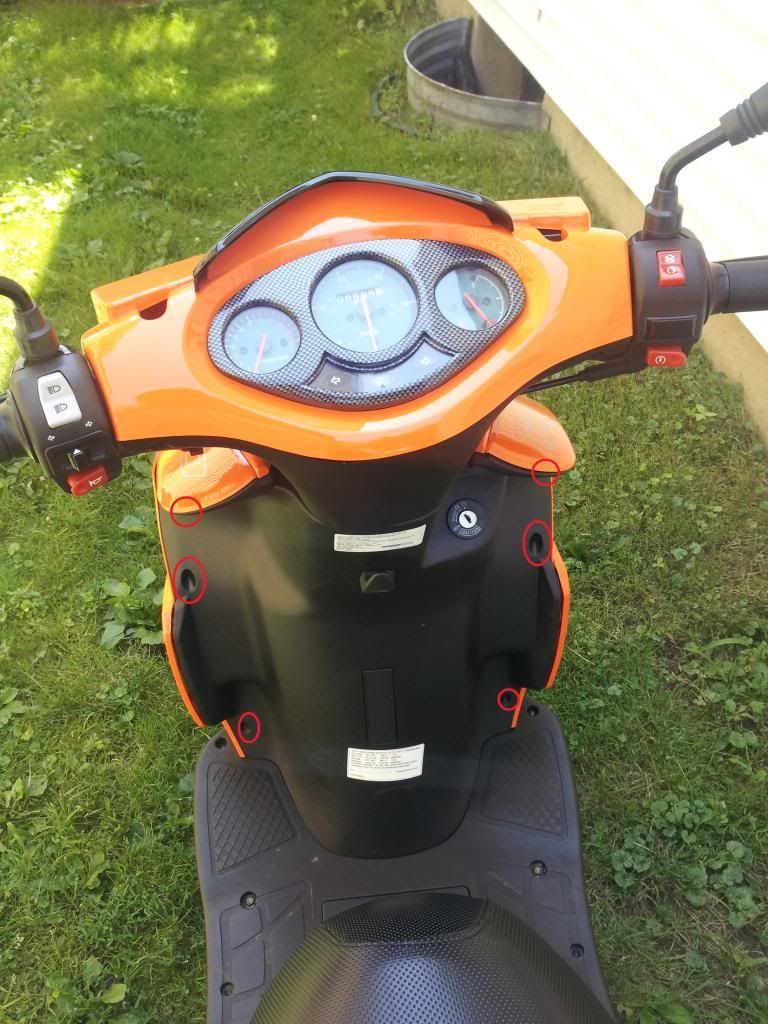 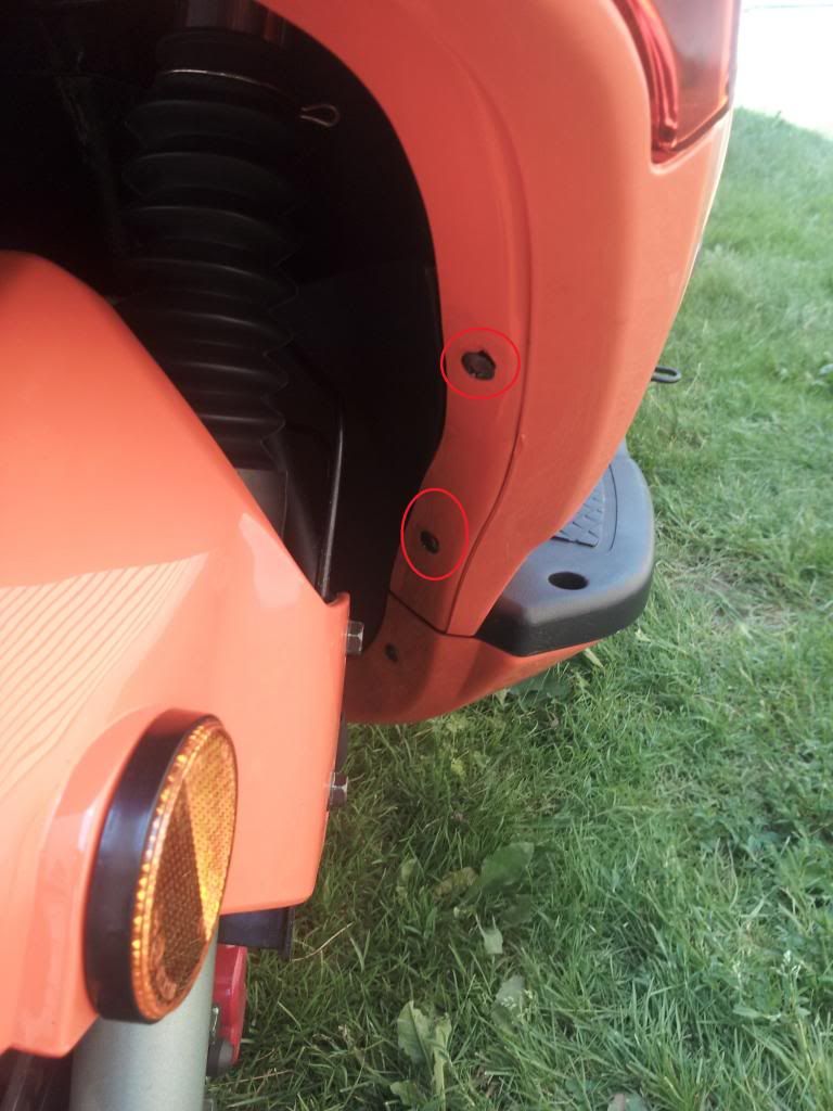 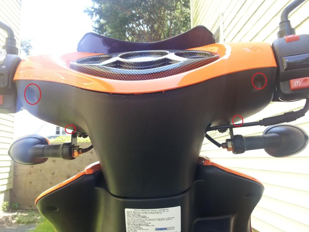 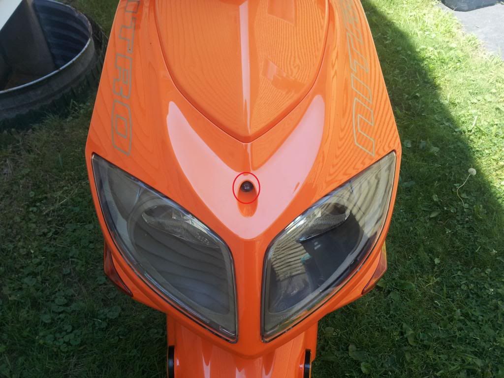 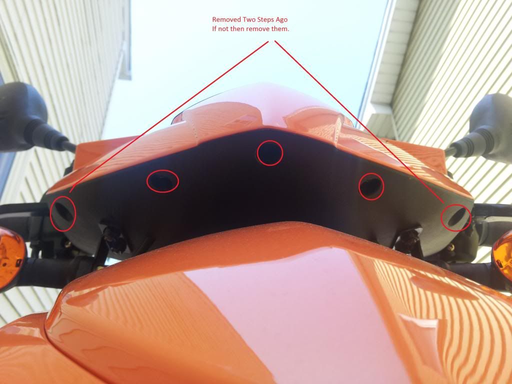 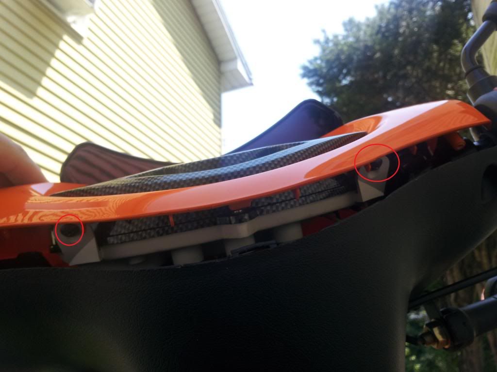 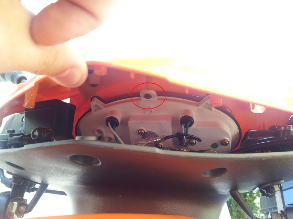 Step Two: Locate the main harness and find the blinker wires the circles indicate where the blinker wires are coming from, (the under the handlebar blinkers that is): Move the gauge cluster out of the way first- 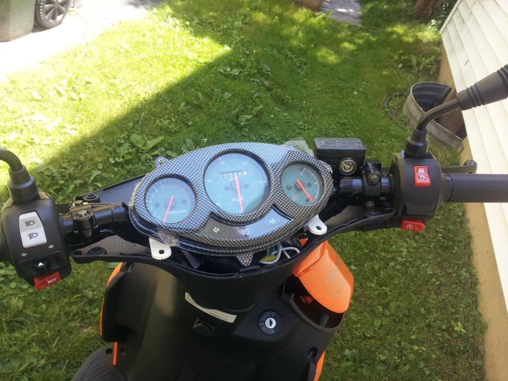 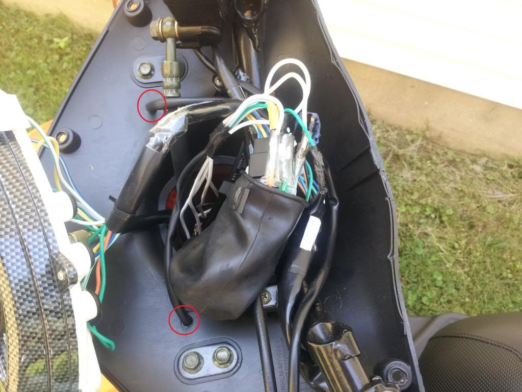 The left orange wire was the positive to the left blinker, the right sky blue wire was the positive to the right blinker, the center green was ground for both, just wire negative from the blubs that you are hooking up to this green wire. You can test your wires by pulling one at a time and turning the blinkers on to see which side that wire belongs to. 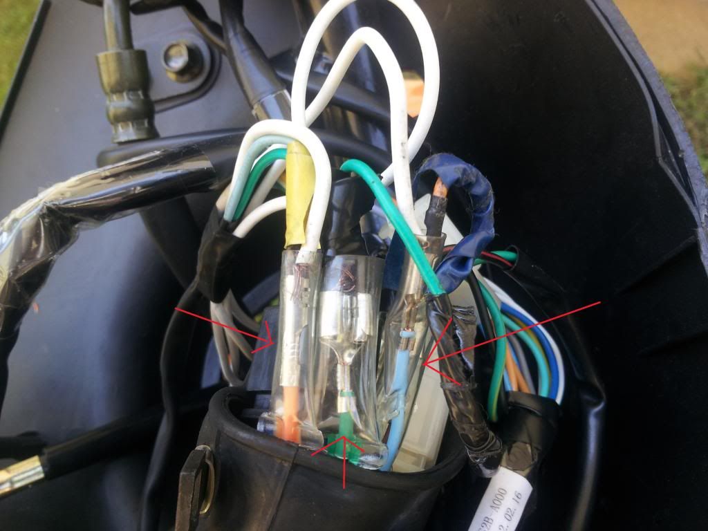 This is the view looking down the steering showing how I put the wires down through. 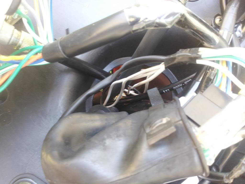 Step Three: Connect the wires to the bulb, note that the middle connection is positive and the outer connection is to the side of the bulb which goes to ground (you can take the housing out or just the bulb): The left arrow is the negative which touches the side of the bulb, the right arrow is the positive which touches the little bump on the bottom of the bulb. 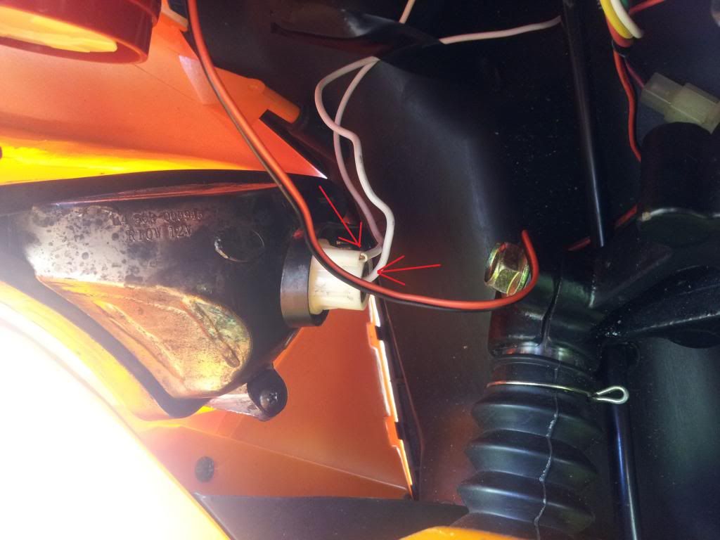 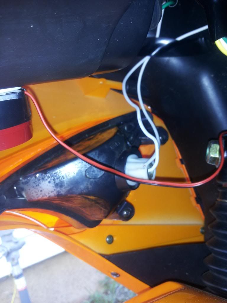 Step Four (Final Step): Test the connections that you have made, they should now work, if they do then just close up in the reverse order that you opened it in, otherwise recheck your connections. I hope that this is detailed enough to help you guys out, if not just ask and I will do my best to clarify. This was done on my 49CC Tomos Nitro 50, but it should be the same if not very similar. GOOD LUCK!  Troubleshooting - If your entire gauge cluster loses power after a crossed wire, check the fuses, mine are located in the battery box. (This was the only problem I encountered.) (if you have any other troubles just reply and I will add on to this troubleshooting guide.) |
|
|
|
07-16-2013, 07:03 PM
|
#8 |
|
Join Date: Mar 2010
Location: Houston area
Posts: 945
|
Thanks for the info dawgs. I'll get some splices on the way home.
__________________
"Beer never broke my heart" - Luke Combs |
|
|
|
07-17-2013, 09:22 AM
|
#9 |
|
Join Date: Jul 2011
Location: Connecticut
Posts: 493
|
GREAT PICS SUPRTIGR!!!
Excellent tutorial! However, I HIGHLY RECOMMEND NOT USING SPLICERS, they are not good because there is a lot of vibration when you are riding and just one short can easily cause a myriad of problems, not the least of which is an electrical fire. Grab a $10 soldiering Iron from a Harbor Freight, some scrap wires and a roll of flux-core soldier, and practice making some nice welds on your scrap wires. Soldiering is an essential skill you will be glad you learned!
__________________
2011 Roketa MC-23-150 4T 150cc 157 qmj 24mm carb w 115 main jet and paper cone air filter Manual petcock w Tygon fuel lines Scrappy Dog Scooters Retro-slash stainless straight-thru exhaust RED spring clutch Adjustable CDI (brand unknown, it's blue and red and works great!) KOSO high performance variator w 12g sliders Gates Powerlink 835-20-30 belt GPS verified 65mph on flats. |
|
|
|
07-17-2013, 12:43 PM
|
#10 |
|
Join Date: Jul 2013
Location: Connecticut, USA
Posts: 15
|
I do intend to solder the connections just wanted a proof of concept for my own eyes to see what I did works. But I plan to go back and solder it in place now I know for sure it didn't give me any bad side effects. Thank you for your advice and also for complements. Will definitely be thinking about posting tutorials in the future.
__________________
 Sally - 2012 Tomos Nitro 50 - Performance CDI |
|
|
|
07-17-2013, 06:29 PM
|
#11 |
|
Join Date: Mar 2010
Location: Houston area
Posts: 945
|
Sounds good. Will splice just long enough to confirm the correct wiring source and then soldier the connections.
__________________
"Beer never broke my heart" - Luke Combs |
|
|
 |
|
|


 Linear Mode

